
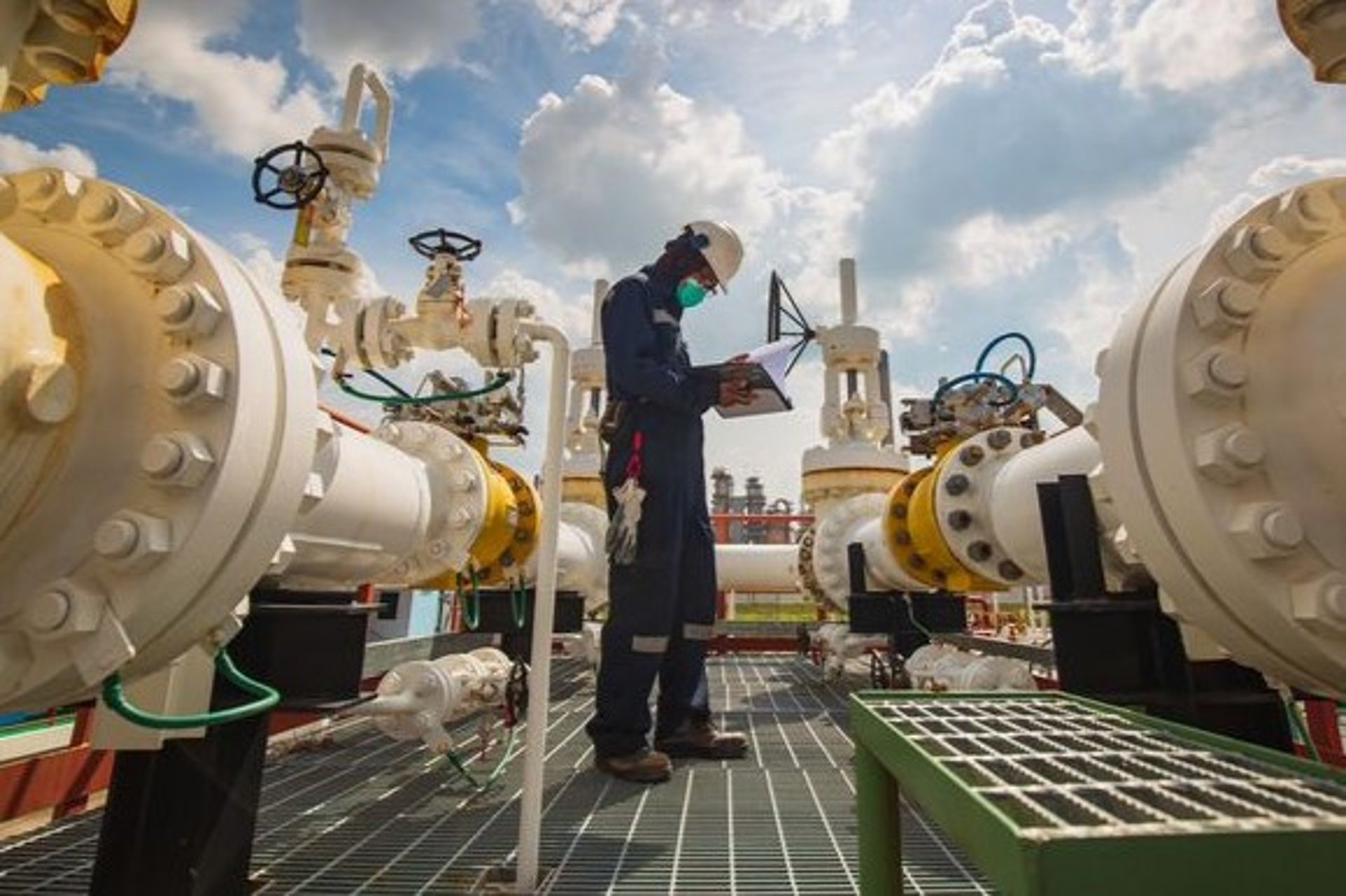
Mechanical, HVAC, Piping & Plumbing
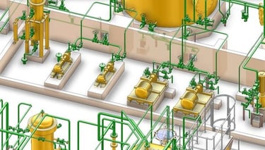
1. Layout Drawing
Definition:
A 2D/3D schematic showing the arrangement of equipment, piping, and structural elements within a facility.
Key Details:
Equipment location (pumps, tanks, HVAC units) with clearance zones
Piping routes with flow directions
Structural supports (steel beams, foundations)
Accessibility for maintenance
Compliance with safety codes (ASME, NFPA, API)
Used in:
Plant design
Facility expansion
Space optimization
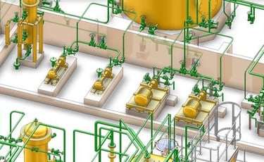
2. Isometric Drawing
Definition:
A 3D representation of piping systems, showing exact dimensions, angles, and fittings.
Key Details:
Pipe routing with coordinates (North/East/Elevation)
Fittings (elbows, tees, valves) with specs
Welding points and support locations
Material specifications (ASTM, ANSI class)
Purpose:
Fabrication & construction guide
Avoids clashes during installation
Software:
AutoCAD Plant 3D
SmartPlant 3D
CADWorx
3. Requisition
Definition:
A formal request for materials, equipment, or contractor services.
Contents:
Technical specifications (material grade, pressure rating)
Quantity (length, size, units)
Delivery schedule
Quality requirements (certifications, testing)
Types:
Material Requisition (pipes, valves, insulation)
Equipment Requisition (pumps, chillers, boilers)
Approval Flow:
Engineer → Procurement → Vendor
4. Flexibility Analysis (Stress Analysis)
Definition:
Ensures piping systems can withstand thermal expansion, vibration, and pressure loads.
Key Checks:
Expansion loops vs. expansion joints
Pipe stress at anchor points
Nozzle loads on equipment
Support types (rigid, spring, hangers)
Software:
CAESAR II
AutoPIPE
ROHR2
Output:
Stress report with acceptance criteria (ASME B31.3)
Support adjustment recommendations
5. Information Drawing
Definition:
Summarizes key data for construction and maintenance.
Includes:
P&ID references
Equipment datasheets
Valve schedules
Insulation/thickness details
Purpose:
Quick reference for field teams
6. Test Block Diagram
Definition:
Outlines pressure testing procedures for piping systems.
Details:
Test medium (water, air, nitrogen)
Test pressure (1.5x design pressure)
Isolation points
Safety valves
Standards:
ASME B31.1 (Power Piping)
ASME B31.3 (Process Piping)
7. MTO (Material Take-Off)
Definition:
A bill of quantities extracted from drawings.
Breakdown:
Item Specs Qty Unit
CS Pipe 4" Sch 40 ASTM A106 150 meter
Gate Valve 4" 150# RF 8 ea
Uses:
Cost estimation
Procurement tracking
8. HVAC-Specific Documents
Duct Layout Drawing
Shows airflow paths, dampers, diffusers
CFM requirements per zone
Psychrometric Analysis
Calculates cooling load (sensible/latent heat)
Chiller/Pump Schedules
Capacity (tons, kW)
Flow rates (GPM)

Services
Visit us
Jalan Batik Halus No.10A Sukaluyu Kota Bandung, Jawa Barat 40123
© 2026 All rights reserved.
Address Bandung
location
Address Jakarta
GIESMART PLAZA
Jl. Raya Pasar Minggu No.17A 7, RT.7/RW.9, Pancoran, Kec. Pancoran, Kota Jakarta Selatan, Daerah Khusus Ibukota Jakarta 12780